RD Controls Hardware Release Note 28.2
<P>
Preliminary Design
<P>
C1080 Multibus Interface Module
<P>
CAMAC Function Codes
RD Controls Hardware Release Note 28.2
Preliminary Design
C1080 Multibus Interface Module
CAMAC Function Codes
R.E.West
September 1, 1992
Introduction
The beamline control system interfaces with modules residing in
multibus crates used to obtain information from and to
control devices in the various beamline cryogenic systems. A
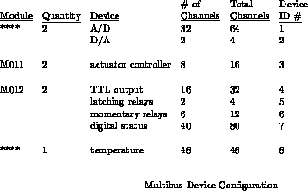
cryogenics multibus crate may contain a maximum of two A/D-D/A modules,
two actuator controller modules, two digital status and control modules, and
one temperature resistor module.
An A/D-D/A module contains 32 A/D data channels
and 2 D/A channels. For interfacing purposes, the A/D section and the D/A
section are each identified as a separate device having multiple data channels.
Because there may be two A/D-D/A modules in a multibus crate, the A/D device
is considered to have a maximum of 64 (2 * 32) data channels and the D/A device
is considered to have a maximum of 4 (2 * 2) data channels. The other
multibus module which is treated as a collection of distinct devices is the
digital status and control module. Using this scheme of devices and channels,
Table 1 lists the maximum configuration a multibus currently may contain.


CAMAC Function Codes
Because a multibus device (e.g., digital status) may have as many as 80
channels, it is not possible
to use only one CAMAC operation to read information from a specific device and
channel. It is necessary to first perform a write operation (F17A0) to
specify the initial channel number. After that, each
read operation directed to a particular device returns the requested
information and then increments the channel number. Note that only one
channel number variable is maintained. Each time data is to be obtained from a
different device, the initial channel number must be specified again. A
minimum of 7 bits is required to specify the largest channel number currently
being used. A field width of 8 bits is actually used, so the maximum channel
number which may potentially be used is 255.
- F0An
-
Read a 16-bit data word and then increment the channel number.
A valid reading is returned only for the A/D device and the
temperature device. A request for any other device or for a
channel number greater than the maximum for the requested
device results in a no Q. The average value is calculated using
the previous eight data readings.
- A0 - read A/D channel
- A1 - read A/D channel averaged over the last 8 readings
- A2 - read temperature channel
- A3 - read temperature channel averaged over the last 8 readings
- F0A12
-
Read the current value of the channel number, which is the number
of the channel to be used for the next read or write operation
directed to the channel of a device. Note that this channel
value will not be the same as the value initially specified if read or
write operations have been issued to the device and have caused the channel
number to be incremented.
- F0A13
-
Read the selected table ID number and the entry offset. Parameter
tables may be associated with particular device and channel
combinations. This operation selects the initial entry
of a particular table to be referenced by a table read
or write operation. As with the channel number variable,
there is only one table/offset variable pair. Hence, the table ID and
initial entry offset need to be specified prior to referencing
parameter table data for a different device.
bits 15 - 8: table ID
bits 7 - 0: entry offset
- F0A14
-
Read a 16-bit data word from the selected parameter table of the
selected device and channel and then increment the entry
offset to the next word. Note that the channel number is not incremented
by this operation nor by the the F1A1.
- F1A0
-
Read engine requested position.
- F1A1
-
Re0d engine tolerance.
- F1A2
-
Read actuator requested position.
- F1A3
-
Read actuator tolerance.
- F1An
-
Read status register and then increment the channel number
- F1A13
-
Read LAM mask
- F1A14
-
Read LAM request register
- F6A0
-
Read module number
- F6A1
-
Read version number
- F6A3
-
Read FOP status
- F6A4
-
Read FOP data
- F6A5
-
Read the hardware serial number of the module
- F8A0
-
Test LAM
- F9A0
-
Module reset
- F10A0
-
Clear LAM
- F17A0
-
Write the channel number
- F17A1
-
Write the table ID number and the entry offset
bits 15 - 8: table ID
bits 7 - 0: entry offset
- F17A2
-
Write a 16-bit data word to the current entry in the selected table
and then increment the entry offset to the next word
- F17A3
-
Write engine requested position.
- F17A4
-
Write engine tolerance.
- F17A5
-
Write actuator requested position.
- F17A6
-
Write actuator tolerance.
- F17A13
-
Write LAM mask
- F17A14
-
Write LAM request register
- F19A2
-
Write FOP command
- F19A3
-
Write FOP data to buffer
- F19An
-
Set to 0 (OFF or OPEN) or 1 (ON or CLOSED) and then increment the channel
number
- A4 - TTL latch (0 = OPEN, 1 = CLOSED)
- A5 - latching relay (0 = OPEN, 1 = CLOSED)
- A6 - momentary relay (0 or 1 = pulse the relay)
- A7 - engine (set of momentary relays)
- A8 - compressor status (set of momentary relays)
- F24A0
-
Disable LAM
- F26A0
-
Enable LAM
Security, Privacy, Legal
rwest@fsus04.fnal.gov
