It is a very common situation when controlled hardware can work in the variety of different regimes, in which case control system has to have certain amount of smarts to be able to recognize the regime change and reconfigure itself accordingly. One of the crucial points here is being able to reconfigure alarms system, so that in behaves appropriatly through all possible regimes of equipment functioning. In practice it usually involves 3 major parts:
The first part is very system specific and for FRIG implementation we've chosen finite state machines mechanism. This mechanism is already build into cryogenic control software, that is why it relatively easy to implement additional finite state machine (FSM), which is dedicated solely to tracking of the cryogenic system parameters and determining of the current regime.
Regime switching mechanism is significantly more generic and is implemented in the form of the Virtual Machines front end (FE), that can be used not only by cryogenic control system but throught the whole control system.
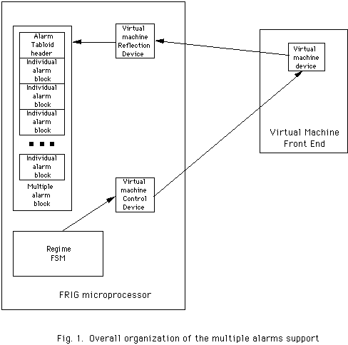
Multiple alarm support itself is supported by FE internally in form of keeping several alarm block for every particular device and tracking mechanism, allowing alarm block switching, based on the regime changing. The overall interaction scheme for the multiple alarms support is given on fig 1.

Several changes have been made to support multiple alarms in the FRIG micro. Two new types of devices were introduced: Virtual machine control and virtual machine reflection. Virtual machine control device comprise two devices - primary and secondary. Secondary device is used for establishing of the link to the Virtual machine FE. It supports 3 data base properties : setting - setting of the DI of the Virtual machine FE device, to which it will be connected, reading of setting - reading set information back, and basic status, acknowledging that the setting to the device has been done. Primary device is used for the setting of the regime itself. It can be set either externally (from parameter page or specialized application) or internally by FRIG software, for example, by the dedicated FSM. When this device receives setting it sends message (via proprietary protocol) to the Virtual machine FE. This device allows to facilitate internal intelligence in FRIG micro, that makes the decisions about state (regime) change. The Database properties, supported for this device are setting - setting of the current regime, reading and reading the setting, that are returning this set value and basic status - the same as for secondary device. The Virtual machine FE, when it receives regime change message, checks it for correctness, and if it is in fact correct, besides doing other things, does the setting to the virtual machine reflection device. The virtual machine reflection device is the one that really controls alarm block changing. In the current implementation we are supporting up to 64 virtual machine control devices and up to 64 virtual machine reflection devices. This framework is flexible enough to provide both internal and external regime switching and inter node communications.
Virtual machine FE is an Open Access Front-end that services requests for state changes of virtual machines. Introduction of this FE allows for centralization of services that support Virtual machine paradigm in the ACNET control system. Upon a state-change request, the Virtual machine FE will set an MDAT transmitter device and notify any registered tasks. State-change requests are usually done by setting a virtual machine device setting. One could imagine also supporting a typecoded ACNET request for state changes.
The description of the virtual machines is contained in ACNET devices, owned by the Virtual machine FE. There will be one device device per virtual machine. G:VMVOID (the NULL machine) is an example device.
Device structure is:
Name: G:VMxxxx; 'xxxx' is specified by the creator of the device
Text: textual description or name of this virtual machine
SSDN: 0006/ddvv/xsns/0000
00 reserved: future use
06 reserved: specifies the STATES front-end
dd domain: MDAT frame number that transmits the state data
vv virtual machine number [1 - 255], 0 is the NULL machine
xs number of maximum state [0 - 255], 0 is the NULL state
ns number of minimum state [0 - 255], 0 is the NULL state
00 reserved: future use
00 reserved: future use
Setting and reading properties have unitary scaling.Basic setting and control contains ON/OFF which ALLOWS/DISALLOWS state changes for the virtual machine represented by that device. STATES changes the MDAT transmitter by setting a 'hidden' 256-byte device, which is owned by whatever front-end the transmitter is connected to.
For a task to receive notification of a state change, it must have registered with Virtual machine FE via a typecoded ACNET request containing the Device Index of the virtual machine of interest. Whenever there's a state change for the specified machine, FE will send notification either via an ACNET USM or by setting specified virtual machine reflection device.
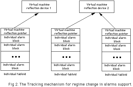
Multiple alarms support is achieved by replacement of the alarm blocks by alarm tabloids, each containing 16 alarm blocks (digital or analog), thus allowing to support up to 16 different alarm blocks per device/property inside FRIG. Every tabloid has a pointer to the virtual machine reflection device, by which it is controlled. This hierarchical scheme is established in the Database, by introducing additional property - PRVMDI. For given device this property defines Virtual Machine FE device controlling it and the set of the controlled properties (Analog Alarms, Digital Alarms, Settings, etc.). Given Virtual machine FE device, it is possible to query Virtual machine FE to determine Virtual machine reflection device for the given node, that actually fulfills local regime control. This hierarchy can be downloaded into the microprocessor either by using Frigboot (Database download) or specialized alarm viewer application (D67). D67 also allows for queering this hierarchy from the FRIG microprocessor. Specialized proprietary protocol is used to support downloading and read back of hierarchical information. Each time, when alarm scan is fulfilled, the value of the virtual machine reflection device is obtained and this value serves as an index into array of alarm blocks for this particular tabloid. The virtual machine reflection device itself, in this implementation, doesn't have to know about alarm tabloids it is controlling. This allows to have connection pointers only in tabloids themselves and eliminates necessity of maintaining the linked list of tabloids, belonging to each particular virtual machine reflection. The overall regime tracking mechanism is shown on FIG. 2.

There are several caveats here. In order not to lose information when state switch occurs, tabloids, besides described thing contain current state in which they are, current GOOD/BAD status, and current "message send to Aelous" state, thus allowing smooth state transition. Whenever state transition occurs, tries needed are set to 0 and then they are adjusted according to the normal alarm processing procedure. In the abnormal situations when the Virtual machine reflection device is getting in the state for which alarm block doesn't exist microprocessor is producing an alarm. This is event type alarm that is hooked up to the virtual machine reflection device. Besides the name of the Virtual machine reflection device it also shows the EMC of the device that has problems. The timing scheme for this alarm is set up so that we are guaranteed that alarm of this type won't be produced faster then every 3 minutes and for each individual device we won't have alarm of this type faster than every 6 hours. This was done in order to prevent the possibility of the alarm storm if machine is getting into the unsupported state.
The way in which the application sees multiple alarm block is shown on fig 3.

Here "current" stands for the alarm block to which virtual machine device is pointing and the length of each alarm block is 20 bytes. If application is trying to do settings with the offset that is less then 20, the settings is done for the "current" alarm block. In this case FRIG will change the original offset insuring that this setting will be forwarded to the appropriate alarm block in the DB. If setting is done to the "current" alarm block length+offset should be within 20 bytes limits. If the offset is greater than 20 then "real" alarm blocks are set. In this case one setting can set several alarm blocks. The same is true for readings.
Data base support for the multiple alarms consists of two parts:
Support for the alarm array assumes that instead of one alarm block with the length of 20 bytes, multiple alarm blocks (20 bytes each) can be associated with every alarm property (analog/digital alarms). Database support the same "view" of the alarm block tabloid as an external application, exept that alarm block 0 is not defined in the DB, and data returned for this block is undefined.
PRVMDI is new property introdused specially for multiple alarm support. It is generalized, so that it can be used for support of any property. This property consists of 64 bit field. Lower 32 bits are used for the DI (one per real device)of the VM FE device, that is doing actual state transition. Using this DI application can querry VM FE about virtual machine reflection device, associated with with VM FE device and located in the FE of interest. The upper 32 bits are used as property mask and defines which properties are effected by the state transition. This is in fact just a set of bits, each of which can be either 0 or 1. 1 means that this property of the device is affected by the VM device transition. The bit number for the particular property corresponds to the property value. For example, Analog alarm is bit 1, Digital alarm is bit 5, Setting is bit 13 and so on.